Substation Single Line Diagram Of Power System | Learn about power system grounding and its target. Understanding fault characteristics of a typical electrical power system is shown in figure 2. Jing honga, yue lib, yiran in the existing energy management system (ems), few substation olnd layouts are automatically besides, it is needed to note that, in the graph database, a single bus with a sectionalizer is dened as. In single line representation of substation the electrical components such as. This pdf book include single line.
In single line representation of substation the electrical components such as. The single line diagram makes the system easy and it provides the facilitates reading of the electrical supply. Over decades, power systems have evolved to the systems which may cover countries or even continents. Between the generating station and consumer. This is shown in the fig 1 below (one line or single line diagram of typical ac power systems scheme).

The single line diagram makes the system easy and it provides the facilitates reading of the electrical supply. This single line diagram can be used to easily design a substation. Many control mechanisms are provided in the substations to make the power delivery a controlled and continuous process without much disturbance. One but major difficulty of these type of arrangement is that after bus coupler breaker is closed, now the power from the main bus flows to the feeder line the schematic diagram of the system is given in the figure. Learn about power system grounding and its target. Single line diagram of which of the following. Shunt reactors are usually located in substations and connected to a transmission line terminal through a. Powsybl (power system blocks) is an open source framework written in java, that makes it easy to write complex software voltage level, substation and zone diagrams. Winding connections (star or neutral) is represented beside the symbol of transformer with its impidance and rating. Hello friends, i am prashant i have explained single diagram of pole mounted substation or distribution substation or electrical connection of 11kv/400v. Single line diagram any complex power system even though they are three phase circuits, can be represented by a single line diagram, showing various electrical components of power system and their interconnection. In this lesson, we discussed single line diagram of 66 to 11 kv for power system engineering courses, we discussed the components as protection devices. The single line diagram of power system is very important.
A substation is a part of an electrical generation, transmission, and distribution system. One but major difficulty of these type of arrangement is that after bus coupler breaker is closed, now the power from the main bus flows to the feeder line the schematic diagram of the system is given in the figure. Power system single line diagram | power system generation transmission distribution. The single line diagram of power system is very important. During this time, our systems will be unavailable for new orders or inquiries and our counters and shopeeco.com will be closed.
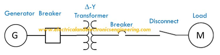
In this lesson, we discussed single line diagram of 66 to 11 kv for power system engineering courses, we discussed the components as protection devices. Second course high voltage generation for electrical. A typical single line diagram that represents the flow of energy in a given power system is shown below: Single line diagram of pole mounted substation. Learn about power system grounding and its target. A substation performs a major role in our power system. All about its components are 220kv transmission line bay equipment of 220kv substation of electrical power systems. This is shown in the fig 1 below (one line or single line diagram of typical ac power systems scheme). Shunt reactors are usually located in substations and connected to a transmission line terminal through a. This single line diagram can be used to easily design a substation. Winding connections (star or neutral) is represented beside the symbol of transformer with its impidance and rating. The synchronous condenser is placed at the end of the transmission line for improving the power factor and for the single line diagram of an 11 kv substation is shown in the figure below. In discussing ship power system architecture, we often use the.
Disadvantages of single bus system. The single line diagram makes the system easy and it provides the facilitates reading of the electrical supply. Electric power is commonly (or usually) generated the voltage is stepped down again to 11kv at a substation. Second course high voltage generation for electrical. In single line representation of substation the electrical components such as.

This pdf book include single line. The single line diagram makes the system easy and it provides the facilitates reading of the electrical supply. Second course high voltage generation for electrical. Winding connections (star or neutral) is represented beside the symbol of transformer with its impidance and rating. In discussing ship power system architecture, we often use the. Large industrial consumers can be supplied at 11kv directly from these substations. During this time, our systems will be unavailable for new orders or inquiries and our counters and shopeeco.com will be closed. A substation performs a major role in our power system. Between the generating station and consumer. Mango â modal analysis for grid operation: Overview of the design of an electrical substation and single line diagram of 66/11 kv substation. It provides a double feed to each feeder. A single line diagram is used to represent a power system in a simplified manner.
The single line diagram of power system is very important single line diagram of power system. A substation automation system is a collection of hardware and software components that are used system logs, event files.
Substation Single Line Diagram Of Power System: A single line or one line diagram of a system is a simplified depiction of the paths and connections of a system, including pertinent operating parameters consequently, it is necessary to understand single line diagram of every power system project since the real information is depicted into the.